6 Methods of Optimizing Carbon Fiber Composites with Tailored Fiber Placement
by Dr. Christopher Anderson, ZSK Research & Training Center Seattle, WA, USA
While the price of carbon fiber has been rapidly decreasing in recent years, it still remains an expensive and highly sought-after material.
Carbon fiber composite material properties such as a high strength to weight ratio, are increasingly being sought to be applied to the next generation of fuel-efficient transportation. Decreasing the weight of a vehicle, plane, or spacecraft, can significantly impact its fuel efficiency over its expected lifetime. Increasingly, carbon fiber is being researched as a replacement to some aluminum structures specifically due to the weight savings it holds. However, the high upfront materials cost of carbon fiber composites can dissuade potential users from adaptation.
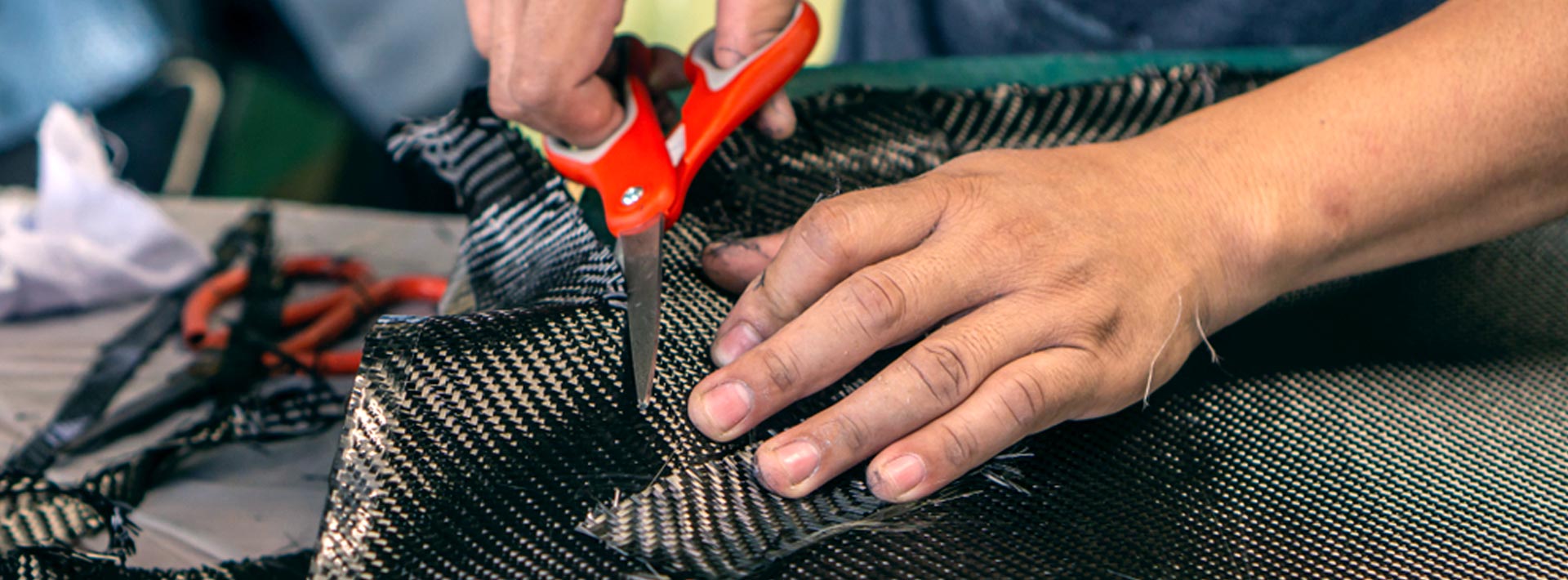
Additionally, the manufacturing of traditional carbon fiber composites has required more processing involvement than aluminum. In one traditional process, woven carbon fiber fabrics have been traced in CAD, cut to scale, wetted with matrix material, and allowed to cure to shape in processes such as Resin Transfer Molding (RTM). However, these processes are often more labor expensive, and lack the automation seen in competing processes such as metal milling or sheet metal bending.
The technique of tailored fiber placement can be applied to the creation of new carbon fiber composite parts in a material and process efficient manner to significantly reduce cost. Tailored fiber placement allows for the reduction of waste carbon fiber material reducing material costs. It also allows for the combination of other fibrous materials in select locations, allows for the fibers to be tailored to the specific loading applied, allows for variable thickness through the parts, and can easily be used with new classes of fibrous technical materials.

Additionally, tailored fiber placement machines require little to no retooling to produce vastly different parts from batch to batch allowing a more versatile manufacturing process. The optimizations provided by tailored fiber placement can help carbon fiber composites increasingly become more cost competitive.
Optimization 1
Reduce waste material
One of the leading material costs of many traditional carbon fiber composite construction techniques includes the large amount of waste material generated. In many hand lay-up processes that use carbon fiber woven material, waste materials can easily account for 50% or more of the total weight of carbon used. This waste is generated as the fabric is initially cut before impregnation with the matrix material. Additional waste is generated after the composite has cured during the post processing steps where the shape is further refined.
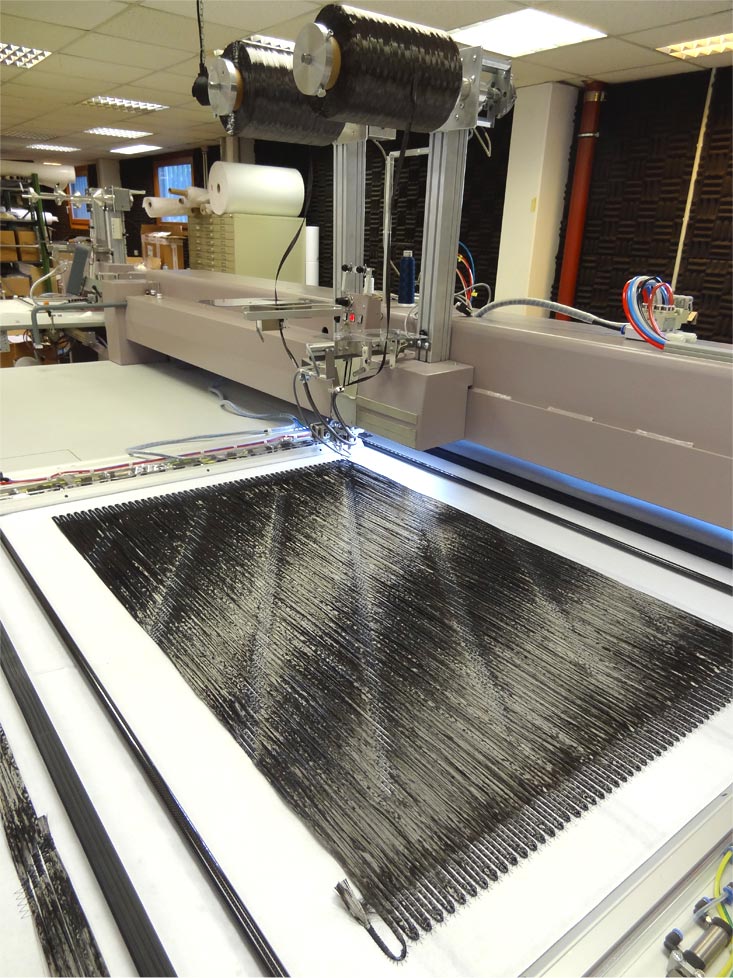
Tailored fiber placement is unique in its ability to reduce waste material and thereby optimize material cost. By controlling the path of the tow material as it is stitched into the desired geometry, material is only placed where it is needed in the final preform. Areas of fabric that would have to be cut out in traditional laminate design are simply left unstitched. This process reduces both the initial waste produced when cutting woven fabrics to shape, and also reduces post processing waste due to the ability to conform to complex geometries.
Optimization 2
Hybrid carbon fiber and glass fiber composites
An additional drawback of traditional laminate processes is the inability to rapidly change materials volumetrically to benefit from their combined advantages. Tailored fiber placement is a method for quickly and effectively creating these multi-material composites.
For example, when a structural analysis is performed on a part, it might be discovered that the part only requires areas of localized stiffness. In this case, carbon fiber, with its properties of high stiffness, can be placed exactly at the areas and geometries of the part requiring high stiffness. It would be cost-inefficient to fill the entire part with highly stiff carbon fiber, especially when that stiffness is not required in certain locations. Therefore, to further reduce cost, the areas around the carbon fiber stiffened geometry that do not require high stiffness can be filled in with lower cost materials such as glass fiber or even hemp fibers. Tailored fiber placement allows these material transitions to seamlessly occur.

Optimization 3
Tunable fiber alignment and geometric tailorability
Once of the largest benefits of using tailored fiber placement to optimize a design, is the ability to precisely control where each tow of carbon fiber is placed in a design. This allows the composites designer to further optimize the materials properties, reducing the need for additional material.
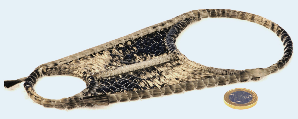
For example, complex tow paths of carbon fiber can be embroidered to perfectly resist the applied loads. By aligning fibers to their principal stresses, additional mechanical support is provided without using additional material. Further optimizations can occur by selectively reinforcing holes and circular drill points. In traditional laminate design, these holes can serve as areas of crack propagation due to the orthogonal nature of the woven fabric used. Tailored fiber placement can be used to selectively reinforce around these holes with curvilinear patterns reducing the effective initial crack propagation locations. This can allow for a thinner material at the hole’s location, and even potentially the removal of metal reinforcing washers.
Optimization 4
Tunable localized thickness
Another interesting optimization that can occur when using tailored fiber placement in carbon fiber composites utilizes tunable thickness of the process over a given area. In traditional laminate design, carbon fiber composites are presumed to have even thickness. However, tailored fiber placement does not have such a height restriction. In combination with well designed molding and fixtures, carbon fiber preforms can create localized thickness in highly complicated and varied geometries.
In classical beam theory, the moment of inertia for a rectangular beam can be calculated by:

Where the height of the material (h) is shown to have cubic influence on the moment of inertia when compared to the base (b) length. This means that localized areas of height can be created with tailored fiber placement that significantly can help to better resist bending at that location. This optimization allows for decreased material usage to achieve the same, if not improved, bulk material properties when compared to other composite processes.
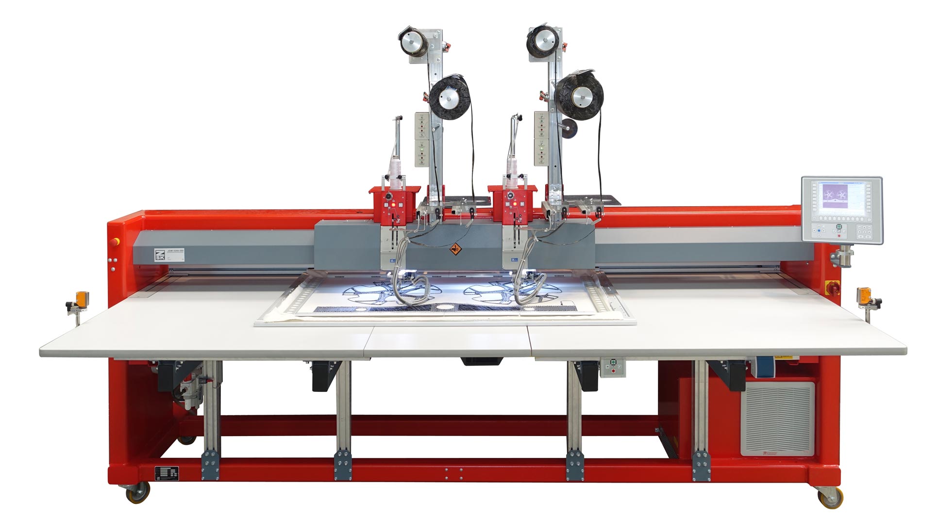
ZSK STICKMASCHINEN offers machines that can lay fibers up to 8 mm thick. This averages out to about 8 layers of 50 K carbon fiber roving. This thickness can be uniform over the entire surface of the preform part, or can be selectively placed in key structural areas for additional material conscience mechanical support.

Thickness is built around the perimeter and in the center of the part. This additional thickness allows the part to better resist an applied bending moment while reducing material cost by not reinforcing areas that do not require additional support. Additionally, curvilinear placement of carbon around the holes helps to minimize crack propagation often seen in orthogonal woven sheet laminate design while also reducing potential post processing and waste material.
Optimization 5
Commingled fibrous materials
One of the drawbacks of traditional composite laminate manufacturing can be the long cycle times required to properly cure a thermoset resin. New materials, called comingled fibers, have been created to decease the processing time. In comingled fibers, a carbon fiber tow has additional thermoplastic matrix materials added directly into its fiber structure.
These comingled materials can be stitched in the same manner as other tailored fiber placement composite materials. However, these preforms can quickly be thermocycled in heated presses to rapidly reduce the cycle processing time. Traditional thermoset composite materials using resin transfer molding can require between 30 minutes to 40 hours to properly set and cure a single piece.
Tailored fiber placement of comingled materials allows for the placement of both the reinforcing fiber, and the matrix material in the same preform. As the preform is heated, the liquid matrix is distributed directly into the carbon fiber allowing proper wetting. The tailored fiber placement of comingled fibers eliminates the need for additional resins and can significantly reduce materials cost. Additionally, the desired fiber to volume fraction is created during the comingling step, increasing the uniformity of the composite material from batch to batch.
Finally, these comingled fiber composites are a step towards a more sustainable carbon fiber composite due to their ability to be re-melted into new forms at the end of their lifecycle.
Optimization 6
Machine versatility without retooling
Another significant process optimization that occurs with tailored fibre placement when compared with other composite processes, is the ability for the production machine to rapidly change its production from one design to a completely different design without any additional retooling of the machine. This can allow the same machine to seamlessly transfer from producing car parts in the morning shift to sporting equipment in the afternoon shift.
Additionally, tailored fibre placement can allow the same machine to produce one prototype design at a time to investigate a process and troubleshoot it without wasting excess material, to creating a full production run simultaneously. This rapid prototyping to production capability, in combination with the ability for a machine to run many different types and geometries of parts in rapid succession, allows for more versatile projects to be run on the same machine. This reduces the cost of setting up a new machine each time a new design is generated.
In conclusion, the six methods of optimization for carbon fibre composites briefly presented show some of the advantages of tailored fibre placement over traditional composite processes. It is hoped that the combination of these optimization methods, in conjunction with a trend of decreasing carbon fibre material costs, will allow a new class of ubiquitous and highly engineered materials to further improve consumer use cases like fuel efficiency.
ZSK offers machines for tailored fibre placement (or TFP) for a variety of part sizes and base case scenarios. Prototyping machines are available with 1 head to quickly produce new prototypes with minimal setup time or material commitment, while production machines are available with up to 11 heads that can simultaneously lay fibres for mass production. The usable machine field area for an 8 head machine is 900 mm x 1,900 mm per head. This means, as long as the part fits within the 900 mm x 1,900 mm area, it can be created and duplicated 8 times simultaneously per run. For larger parts that do not fit within this area requirement, an 8 head machine can be reconfigured to a 4 head extended machine within a few minutes on-the-fly. This allows a maximum part size of 1,800 mm by 1,900 mm. Other customizable solutions exist including roll to roll, and specialty placement machines for even larger parts.

